Let’s make your
first build.
Design the layout, test one connector, then make the parts.
Watch the Builder in action.
See a structure take shape, adjust the parts, try Scene mode, check the scale and export the matching project files.
Complete Builder demonstration · No sound
Measure your boards.
In Board setup, choose side lengths and enter your board’s depth and measured thickness. Don’t rely on the thickness printed on the label.
- Length
- Sets the basic cell sides. Custom sides separates horizontal and angled lengths. Use the PDF for final cuts, including longer continuous boards.
- Depth
- Front to back across the broad face. This sets the shelf depth.
- Thickness
- Across the narrow edge. Measure the actual board because the connector fits around it.
Planning around an object? Measure it first, then size the build around it.
Build the layout.
Use Add cell to grow the design, or Add board to add a shelf or close an edge. Rotate the view to see how the pieces meet.
Check the scale.
In Build, open Reference objects for a human size reference.
Try it with everyday objects.
Switch to Scene and drag objects onto the structure. Adjust their size and position to explore the layout.
Scene mode is a visual check, not a load test. Its objects don’t change the board or connector parts list.
Open the Builder →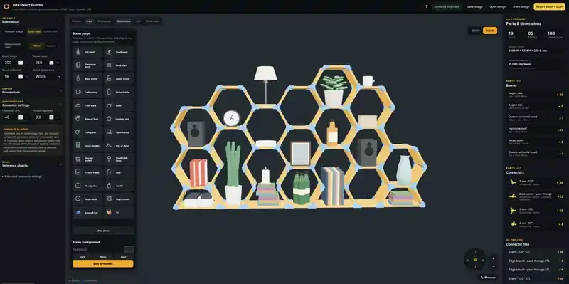
Try one connector first.
Print one connector and try it on an offcut of the same board before making the full set. Start with a small test design so you can check the print and the fit.
- Look
Check the print.
Look for cracks, split layers or rough areas that stop the board seating properly. Don’t use damaged parts.
- Try
Seat the board.
Check that it reaches the stop and feels secure. Don’t force a tight joint or rely on a loose one.
- Adjust
Recheck, then retry.
If needed, check the measured thickness and printer calibration. Change one thing at a time and print another test.
Board fit clearance or Fastener hole tolerance?
Board fit clearance changes how much room the connector leaves around the board. Adjust it in the Builder until a test connector fits your actual board snugly without being forced.
Measure your actual wood and enter it as Board thickness. Print one connector and try it on that same wood before printing the full set. Too tight? Increase Board fit clearance a little, then print and test again.
Board fit clearance is for the wood. Fastener hole tolerance is for the screws. Two different fits.
Need to fine-tune the grip? The friction bumps are the little raised areas inside the connector. Their settings are under Advanced connector settings. Change one thing at a time and try another test print.
Use fasteners where they help.
Fasteners add extra hold at selected joints. They are especially useful for open shapes and wall-mounted builds.
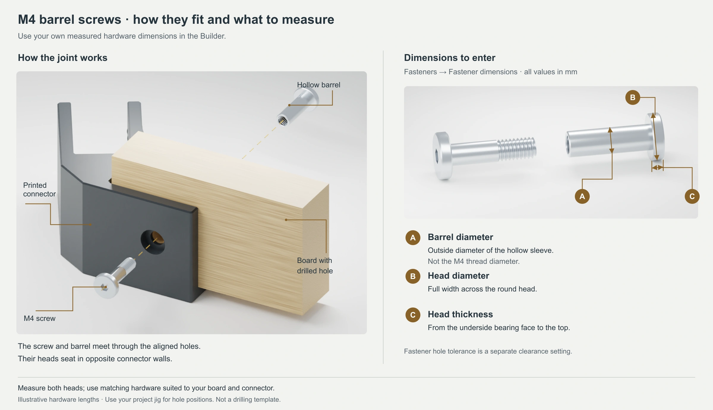
- A Barrel diameter
- Across the outside of the hollow barrel, not the M4 thread.
- B Head diameter
- Across the widest part of the round head.
- C Head thickness
- From the flat underside of the head to its top.
Three steps in the Builder.
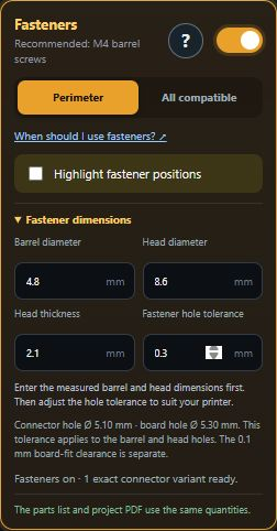
- Turn Fasteners on.Scroll down the left panel to Connector settings → Fasteners. The ? opens the diagram without leaving your design.
- Measure, then enter.Open Fastener dimensions. Enter A, B and C from the picture in millimetres. Fastener hole tolerance adds a little space to the barrel and head hole diameters; it does not change the board fit.
- Choose the joints.Perimeter starts at exposed joints around the shape. All compatible includes other joints with room for the hardware. Use Highlight fastener positions to see where they go.
M4 is the standard recommendation, not a fixed size. M4 names the thread, not the barrel width. Other suitable barrel screws can use measured dimensions within the Builder’s allowed ranges. Check the hardware length and test one joint.
Use the HexaNect hole jigs
The jigs help you mark the hole centres. Their openings are only for marking, not for choosing the final drill size. After marking, use the substantially larger wood-hole size shown in your project PDF. The extra room helps with small marking, drilling and board irregularities.
- Print the Corner jig flat.Place its flat plate on the print bed with both fences pointing up. No supports are needed.
- Fit it over a board corner.Press both fences against the board edges. Either fence can sit on either edge, and the hole stays the same distance from both.
- Mark the centre, then remove the jig.Drill the larger wood-hole size shown in the PDF, then check one complete joint on an offcut first.
Use the Inline jig for a joint along a continuous board. Align its centre notch with the joint mark and its fence with the board edge. Use only the opening that matches the hole in your connector—not both. Remove the jig before drilling, and use the wood-hole size in the PDF.
Keep the pair together The jig spacing changes with your settings. This is a new hole layout, not a guide for older drilled boards or connectors. Export the jig and connectors together.
M4 barrel screws are recommended. The two heads clamp the connector around the board. Avoid countersunk screws; their shape can push printed layers apart.
Tighten gently. Hand-tighten when practical. With a power tool, use low speed and low torque. Fast spinning or binding can create friction heat and soften the connector, so stop if the hardware gets warm or resists.
View recommended M4 barrel screws →Affiliate link. HexaNect may earn a small commission at no extra cost to you.
One download. Matching parts.
Choose Export build package for a ZIP containing your project PDF and printable files. Changed the design or settings? Export again to keep everything matched.
- PDF
Your Project PDF
Parts, quantities, dimensions and assembly views in metric and imperial. B-codes name the boards; C-codes name the connectors. The connector key pairs a 3D picture with the small symbol used on the drawing.
- STL
Your connectors
The printable connector types your design uses. The PDF tells you how many of each to make.
- JIG
Your marking guides
Included when your fastener setup needs them. Use these for hole positions, not the assembly drawing.

Give the fastener room. When fasteners are used, the PDF shows a wood-hole size that is substantially larger than the barrel. Use that size: the extra room makes assembly more forgiving of small irregularities and alignment differences.
Put your first cell together.
- Print
Make the parts.
Use the slicer settings and orientation you checked with the test connector. Print the quantities in your PDF and inspect each part.
- Prepare
Get the boards ready.
Cut to the PDF lengths and remove rough edges. If using fasteners, mark the required holes with the matching jig, then remove it before drilling.
- Connect
Grow it one cell at a time.
Follow the PDF’s board and connector codes. Check each joint as you go, then check the whole piece before putting it to use.
Take your time with the first one. A small build is a useful way to learn how your boards, prints and hardware work together.
Check the joints. Check the wall.
Secure the board joints.
Fasteners are recommended for wall-mounted builds. Wall-mount tabs alone don’t hold the boards in their sockets.
Use suitable wall fixings.
Choose screws and anchors for your actual wall and intended load. Keep wall-mounted builds lighter; don’t assume they can carry the same load as a floor-standing shelf.
Two different screws: a barrel screw holds the board inside the connector; a wall screw attaches the connector to the wall. The wall screw hole has a small bevel at the head-side edge, not a full countersink.
Your first hexagon is waiting.
Start small. See where it takes you.